文章內容
Interferometric Modulation Display (IMOD)

❒ Interference
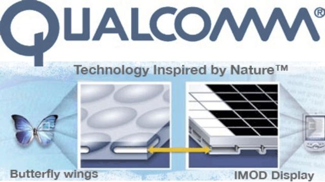
The butterfly wings have beautiful colors, because there are a lot of tiny holes in the wings forming the resonance cavities of light wave. The sizes of resonance cavities are different, so the incident light and reflected light may generate constructive interference or destructive interference. The interference phenomenon between incident light and reflected light may be used to produce a display, called Interferometric Modulator Display (IMOD).
The interaction between two light waves is called interference. Scientists discovered that the butterfly wings have beautiful colors because there are a lot of tiny holes in the wings forming resonance cavities of light waves. The so-called “cavity” is a structure in which the light may be reflected back and forth. Due to different sizes of resonance cavities, the incident light and the reflected light may have two different types of interference:
➤ Constructive interference: The incident light and the reflected light have the same phase in the cavity, i.e. the same waveform. Because the maximum amplitude of the incident light (as indicated by blue arrow) and the maximum amplitude of the reflected light occurred at the same position and would be superimposed, the amplitude of reflective light will be enlarged, as shown in Fig. 1(a).
➤ Destructive interference: The incident light and the reflective light have a phase difference of 180 degrees (complementary waveform to each other), so the maximum amplitude of the incident light (as indicated by blue arrow) and the minimum amplitude of the reflected light occurred at the same position and would be cancelled by each other, and thus the amplitude of reflective light will be reduced, as shown in Fig. 1(b).
.jpg)
Figure 1: Principle of Constructive interference and Destructive interference.
❒ Structure of IMOD
The butterfly wings have many tiny holes causing the light generating interference that the human eyes may see various colors, as shown in Fig. 2(a). The interference between incident light and reflective light may be utilized to produce a display, called Interferometric Modulator Display (IMOD).
➤ Bright and dark displaying: If the energy of different light waves is increased due to interference, it is called “constructive interference,” and the brightness will be increased; if the energy of different light waves is weakened due to interference, it is called “destructive interference,” and the brightness will be reduced. This principle may be utilized to control brightness and darkness, as shown in Fig. 2(b).
➤ Color displaying: Scientists discovered that the natural light may form different colors due to interference. The interference may be used to turn the natural light into the light in different colors after reflection, so as to display different colors.
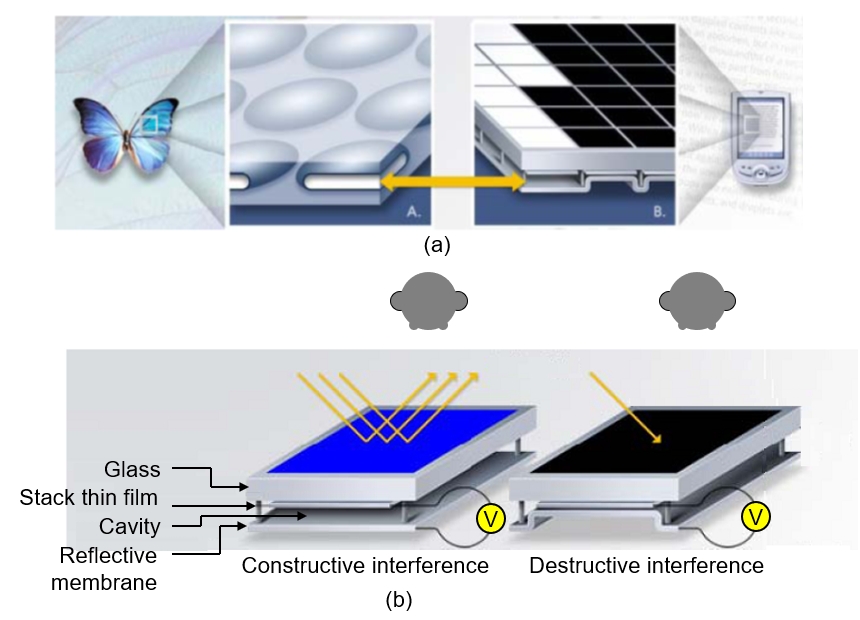
Figure 2: Structure of IMOD.
Source: www.qualcomm.com.
❒ Principle of IMOD
In order to cause interference between light waves, scientists utilized a pair of reflectors to create a cavity and place them under the glass substrate, as shown in Fig. 2(b), so-called “Febry-Perot cavity,” which is composed of upper and lower thin films:
➤ Stack thin film: The upper stack thin film is a semi-reflective (semi-penetration) thin film, which may reflect 95% of light and penetrate 5% of light and utilizes the incident light and the reflected light to generate interference.
➤ Reflective membrane: The lower reflective membrane may reflect 100% of light.
The gap between upper and lower thin films is about 100nm, so-called “cavity.” The sunlight or background light, such as interior lighting, is incident from the upper side and may generate resonance and interference due to the back-and-forth reflection by the upper and lower thin films. The brightness of light will be increased due to constructive interference and will be decreased due to destructive interference. Because the upper stack thin film is a semi-reflective (semi-penetration) thin film for penetrating 5% of light, there will be light continuously penetrated from the upper side to enter user’s eyes, and thus we may see the image.
❒ Color displaying of IMOD
Each pixel of IMOD is a component made by Micro Electro-mechanical System (MEMS) processing. Under the glass substrate of each pixel, it is produced with a stack thin film with fixed position and a reflective membrane capable of moving up and down, as shown in Fig. 3(a). a “sub-pixel” unit of red sub-pixels is taken out to describe the principle of IMOD, as shown in Fig. 3(b).
➤ Red color: White light (R, G, B) is incident into the cavity, and then the white light reflected by the stack thin film is R1, G1, B1, and the white light reflective by the reflective membrane is R2, G2, B2. Because the air gap of cavity is at the maximum, R1 and R2 may generate constructive interference, so the brightness of red light may be increased; and, G1 and G2, B1 and B2 may generate destructive interference, so the brightness of green light and blue light may be decreased.
➤ Green color: Applying positive voltage to move the reflective membrane up; at this time, the air gap of cavity is at the next maximum, so G1 and G2 may generate constructive interference, and thus the brightness of green light may be increased; and, R1 and R2, B1 and B2 may generate destructive interference, and thus the brightness of red light and blue light may be decreased.
➤ Blue color: Applying positive voltage to move the reflective membrane further up; at this time, the air gap of cavity is at the minimum, so B1 and B2 may generate constructive interference, and thus the brightness of blue light may be increased; and, R1 and R2, G1 and G2 may generate destructive interference, and thus the brightness of red light and green light may be decreased.
➤ Black color: Applying positive voltage to move the reflective membrane further up; at this time, the air gap of cavity is zero, so the incident light will be fully absorbed to turn into black color.
➤ Recovery: Applying negative voltage to recover the reflective membrane to the original position; at this time, turning back into red color
The stack thin film and reflective membrane made by MEMS processing will possess the “bistability” characteristic. After applying positive voltage, the voltage may be turned off, and the reflective membrane may be still kept at the highest position. At this time, the air gap (cavity) is zero, so the incident light will be fully absorbed to turn into black color, and will be turned into red color by recovering to the original position until applying negative voltage. Such a characteristic may not need to always apply voltage (by turning off voltage) while the IMOD is displaying black color, so the power consumption may be greatly reduced.
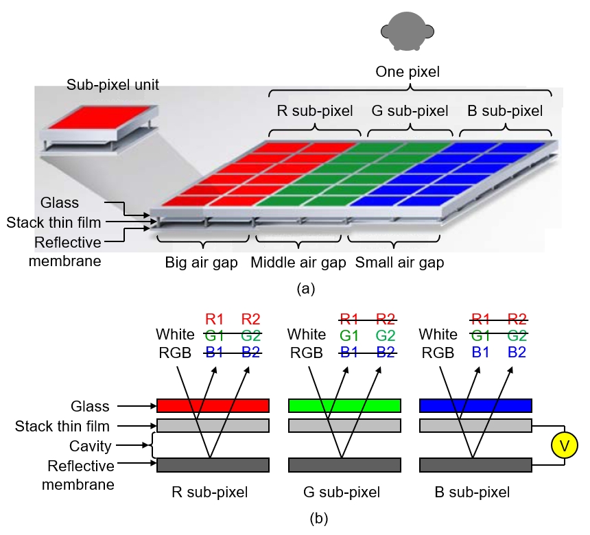
Figure 3: Principle of IMOD.
Source: www.qualcomm.com.
Furthermore, as shown in Fig. 3(a), Red sub-pixel has totally eight “sub-pixel units.” When all the eight sub-pixel units are full bright, it is red color; but, when seven sub-pixel units are full bright and one sub-pixel unit is full dark, it is sub-red color; and so on, so it may display 28=216 different brightness of red color (red levels); similarly, there are 216 different brightness of green color (green levels) and 216 different brightness of blue color (blue levels). Each of the sub-pixel units may be controlled independently to be able to display red color, green color and blue color in different brightness. After arrangement and combination, each pixel may display the full color. This modulation method is called “sub-pixel method (space modulation method).”
❒ Advantage/Disadvantage of IMOD
➤ Advantages
1.Very energy efficient: The stack thin film and reflective membrane made by MEMS processing will possess the “bistability” characteristic, such that IMOD needs not to be always applied voltage (may turn off voltage) during displaying black color, and thus it is very energy efficient.
2. Bright colors: The colors exhibited using interference principle are very bright and beautiful, just like the beautiful colors on butterfly wings.
3. Stable material property: The stack thin film and reflective membrane made by MEMS processing both belong to materials possessing stable characteristic with long service life.
➤Disadvantages
1. Difficult for large area: Due to using MEMS processing, it is not easily to fabricate large-area flat display, so currently IMOD cannot be applied in household TV market.
2. Must depend on background light: Because IMOD must reflect sunlight (background light), the brightness of display is completely determined by the brightness of sunlight (background light) and the image in a dark place will be unclear.
3. Immature processing: The MEMS processing is still under development, so the processing is immature, and has lower yield rate and higher price.
4. Hard to fabricate flexible display: Because the stack thin film and the reflective membrane must be supported in a mechanical manner to prevent cracking, the hard glass substrate is very important and thus IMOD cannot be fabricated using soft plastic substrate and is hardly fabricated as flexible display.
【Remark】The aforementioned contents have been appropriately simplified to be suitable for reading by the public, which might be slightly differentiated from the current industry situation. If you are the expert in this field and would like to give your opinions, please contact the writer. If you have any industrial and technical issues, please join the community for further discussion.
【Picture】www.qualcomm.com.